Cryogenic
Storage Tanks
Overview
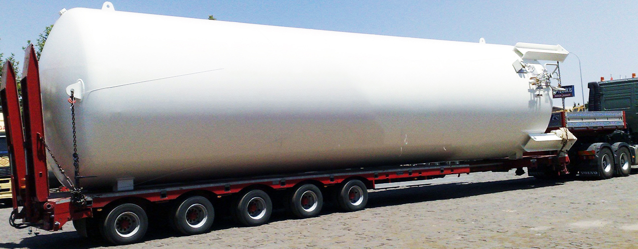
Cryogenic Storage Tanks for atmospheric gases are designed and manufactured for all types of cryogenic applications with the requirements for safe, easy and economical operation.
CrV series tanks are vertical, stationary, pressure vessels with perlite insulation for long-term storage of extreme cold liquids with high quality vacuum level and low evaporation rate.
- Low operation costs by economizer circuit, because the boil off gas is routed into the main system via economizer circuit taken from a top gas connection, which prevents wastage of gas.
- In addition to the standard range of tanks, it can also provide you a wide range of tailor made storage solutions up to 300,000lt with a Maximum Allowable Working Pressure of 19 and 37 bar or other pressures as required.
- Bulk tanks are designed and manufactured in accordance with and conforming to EC directive PED 97 | 23 | CE and EN 13458 or other national pressure vessel codes as required.
- Cryogenic tank manufacturing facility is ISO 9000 approved to assure the best quality in all aspects of our operation.
- The support legs used are calculated according to UBC, Eurocode standards to resist high wind and earthquake loads.
- Carefully designed stainless steel pipe work to reduce filling operation time. Appropriate bending of stainless steel pipe work means fewer connections, minimizing potential leaks, higher operability and less servicing.
- Operational reliability by the mono-bloc pressure building economizer-regulator for easy pressure adjustments.
- High quality stainless steel pressure gauge and differential pressure contents gauge are standard with optional switches, transmitter and | or telemetry unit.
- High performance safety system with dual relief valves by the diverter valves as standard.
- Easily accessible valves and safety relief valve outlets directed away from the operating area, enables safe operation.
- Low installation cost, with the properly designed and oriented lifting lugs.
- All tanks and their components are cleaned for oxygen services.
- Rugged internal supports for safe transportation by road, container or rail.
Tanks highlights are as follows:
Cryogenic
Storage Tanks
Specifications
| Technical Details | ||||
| Design Code | EN 13458 - PED 97 | 23 | EC | |||
| MAWP | 19 | 37 Bar | |||
| Design Temperature | -196° C | |||
| Inner Vessel Material | Stainless Steel (acc. to EN 10028-7) | |||
| Outer Vessel Material | Carbon Steel (acc. to EN 10025 | EN 10028-3) | |||
| Insulation | Pertile and Vacuum | |||
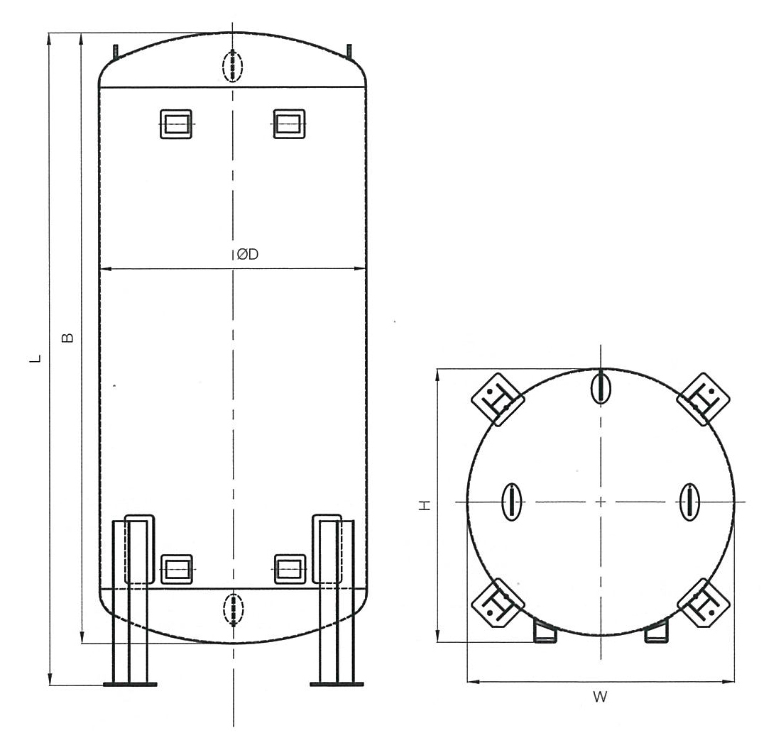
Air Gas Standard Storage Tanks (Dimensions)
| Cryogenic Storage Tanks : LIN | LOX | LAR (19 Bar) | |||||||||
| MAWP | Gross Capacity |
Net Capacity (95% F) |
Daily Evaporation Rate (02) |
0D | B | L | W | H | Empty Weight |
| bar | liters | liters | % | day | mm | mm | mm | mm | mm | kg |
| 19 | 2150 | 2040 | 0.34 | 1700 | 3055 | 3755 | 1920 | 1980 | 2000 |
| 19 | 3450 | 3280 | 0.32 | 1830 | 3320 | 4020 | 2050 | 2120 | 2500 |
| 19 | 6200 | 5890 | 0.30 | 1830 | 5210 | 5910 | 2050 | 2120 | 3750 |
| 19 | 8200 | 7790 | 0.30 | 1830 | 6695 | 7395 | 2050 | 2120 | 4800 |
| 19 | 10450 | 9930 | 0.29 | 2400 | 4640 | 5340 | 2400 | 2690 | 5300 |
| 19 | 14850 | 14110 | 0.28 | 2400 | 6130 | 6830 | 2400 | 2690 | 6950 |
| 19 | 20450 | 19430 | 0.26 | 2400 | 8425 | 9125 | 2400 | 2690 | 8750 |
| 19 | 24750 | 23510 | 0.24 | 2400 | 9925 | 10625 | 2400 | 2690 | 10800 |
| 19 | 31300 | 29735 | 0.23 | 2680 | 9600 | 10300 | 2680 | 3020 | 11750 |
| 19 | 46100 | 43790 | 0.20 | 3050 | 10560 | 11260 | 3050 | 3420 | 18700 |
| 19 | 50000 | 47500 | 0.19 | 3050 | 11300 | 12000 | 3050 | 3420 | 20500 |
| 19 | 56450 | 53630 | 0.18 | 3050 | 12370 | 13070 | 3050 | 3420 | 22200 |
| 19 | 66800 | 63460 | 0.15 | 3050 | 14370 | 15070 | 3050 | 3420 | 25750 |
| Cryogenic Storage Tanks : LIN | LOX | LAR (37 Bar) | |||||||||
| MAWP | Gross Capacity |
Net Capacity (95% F) |
Daily Evaporation Rate (02) |
0D | B | L | W | H | Empty Weight |
| bar | liters | liters | % | day | mm | mm | mm | mm | mm | kg |
| 37 | 3550 | 3370 | 0.20 | 1650 | 4260 | 4960 | 1950 | 1950 | 2950 |
| 37 | 7300 | 6940 | 0.18 | 1930 | 5420 | 6120 | 2200 | 2250 | 5200 |
| 37 | 10500 | 9980 | 0.16 | 1930 | 7740 | 8440 | 2200 | 2250 | 6900 |
| 37 | 15500 | 14730 | 0.14 | 2220 | 7920 | 8620 | 2220 | 2500 | 9700 |
| 37 | 20100 | 19100 | 0.13 | 2220 | 9915 | 10615 | 2220 | 2500 | 12200 |
| 37 | 25170 | 23910 | 0.12 | 2500 | 10300 | 11000 | 2500 | 2780 | 15000 |
| 37 | 31300 | 29730 | 0.10 | 2500 | 11040 | 11740 | 2500 | 2780 | 17000 |
Data given on the table are nominal volumes and actual capacity may vary from these due to manufacturing tolerances.
Cryogenic
Storage Tanks
P&ID
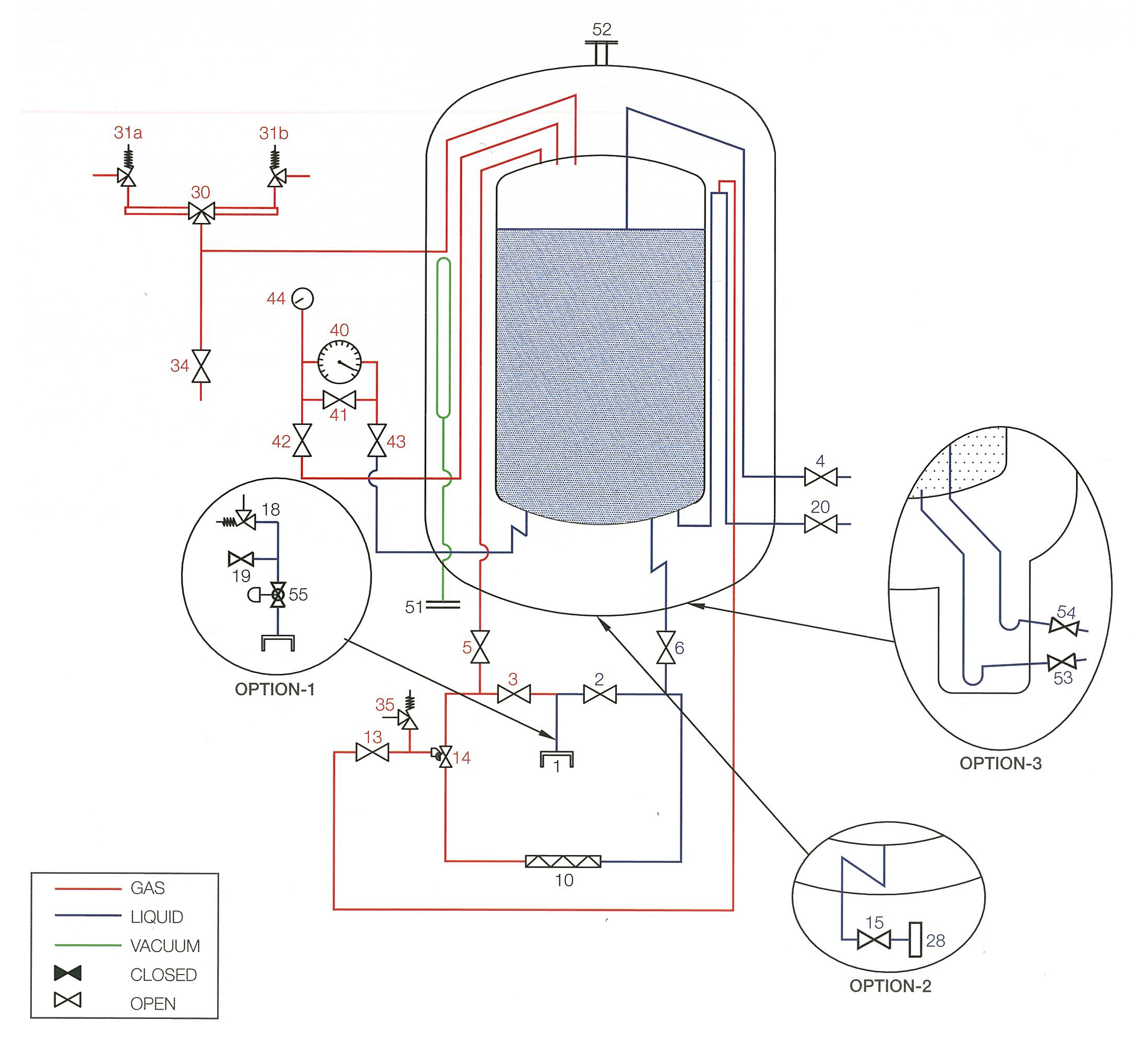
Air Gas Standard Storage Tanks (P&ID)
Salem Industry LLC reserves the right to change above specifications without prior notice.
| Nomenclature | |||||||||
| 1 | Fill Connection | 31 | Inner Vessel SRV (A | B) | OPTN. 1 | Overfilling Protection | ||||
| 2 | Bottom Film Valve | 34 | Vapor Vent Valve | 18 | Thermal Relief Valve | ||||
| 3 | Top Fill Valve | 35 | Termal Relief Valve | 19 | Purge Valve | ||||
| 4 | Try Cock Valve | 40 | Level Indicator | 55 | Overfilling Protection Device | ||||
| 5 | Top Fill Isolating Valve | 41 | Equalizer Valve | OPTN. 2 | Liquid Withdrawal Line | ||||
| 6 | Bottom Fill Isolating Valve | 42 | LPR Shut-Off Valve | 15 | Liquid Withdrawal Valve | ||||
| 10 | Pressure Building Coil | 43 | HPR Shut-Off Valve | 28 | Liquid Withdrawal Connection | ||||
| 13 | Economizer Isolation Valve | 44 | Pressure Indicator | OPTN. 3 | Thermosyphon | ||||
| 14 | Combined Valve | 51 | Evacuation Connection | 53 | Pump Feed Valve | ||||
| 20 | Liquid Withdrawal Valve | 52 | Vacuum Safety Device | 54 | Pump Return Valve | ||||
| 30 | Three Way Valve | ||||||||
Ambient
Vaporizers
Overview
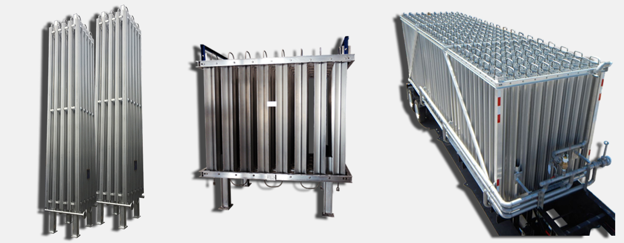
Ambient Air Vaporizers require no external source of energy and enables vaporization through exchange of heat with the surrounding air. The liquefied gas is vaporized, warmed to almost the surrounding temperature and finally led to the users in its gaseous state.
The Vaporizers are for use with Liquid:
- Carbon Dioxide
- Nitrous Oxide
- Nitrogen
- Oxygen
- Argon
- LNG
Design Specifications
It offers a full range of Ambient Air Vaporizers in different versions and applications with the following properties:
- Seismic requirements with accordance to uniform building code-zone 4.
- Optimized external and internal surfaces for optimum convection.
- Designed and manufactured according to PED 97 | 23 | EC.
- Maximum allowable working pressure is 40 bar.
- It is cleaned for oxygen service.
- Efficient fin tube design.
- Low pressure drop.
- It Has CE marking.
Vaporizer Options
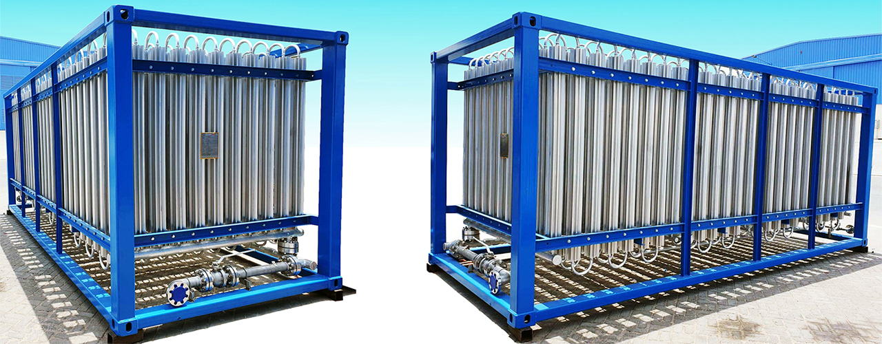
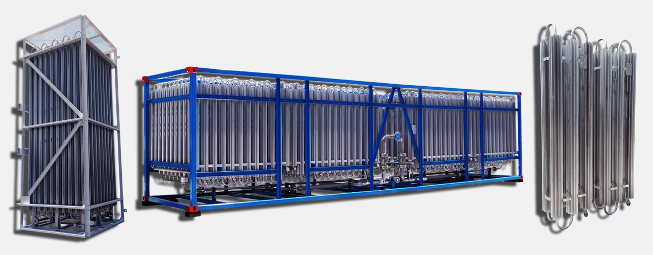
- Fin Tube Vaporizers
- Fan Assisted Vaporizers
Fin Tube Vaporizers rely on natural convection while Fan Assisted Vaporizers are equipped with an electric motor operated fan to enhance the air flow and increase efficiency.
How Do Ambient Air Vaporizers Work?
Since the surrounding air is at a higher temperature than the product, the heat from surrounding air is transferred to the product in the vaporizer.
While Ambient Air Vaporizers are in use, it is normal to see a mist forming. This is caused by the moisture in the air, condensing and freezing. The intense cold of cryogenic liquid and the moisture in the surrounding air will create frost and ice that will build up on vaporizer tubes, gradually.
Therefore, Ambient Air Vaporizers have a limited running time before the frost and ice has to be cleared from the tubes.
The performance of Ambient Air Vaporizers may be impaired during prolonged periods of severe cold weather. This will create additional frost and ice formation, causing a performance drop.
Method of Heat Transfer
✦ Fin Tube Vaporizers
Heat from the air is transferred through natural convection to the vaporizer pipe. The natural convection is created by the temperature difference between the atmospheric air and the air around the cold pipe.
Heat is conducted from the outside of the pipe to the inner wall. Heat is transferred through forced convection from the inner wall to the product. The forced convection is created by the fluid flow in the pipe.
✦ Fan Assisted Vaporizers
Fan Assisted Vaporizers are ambient vaporizers that use a fan to increase the efficiency of the vaporizer. Unlike standard ambient vaporizers, the finned tubes are installed within a framework and are enclosed by walls on all sides. The top normally consists of fan housing with side openings to draw in air. The bottom is kept open. An electric fan in the top of the frame provides forced draught downward over the tubes. Forced convection is more efficient than natural convection, therefore fan assisted vaporizers have better efficiency.
High Pressure
Ambient Vaporizers
Specifications
| Services | ||||
| Manufacturer | Salem Industry LLC | |||
| Equipment Name | Atmospheric Vaporizer | |||
| Type | Vertical | Horizontal | |||
| Fluid | LIN | LOX | LAR | |||
| Operating Inlet Temperature | -196°C + 65°C | |||
| Operating Outlet Temperature | 20°C Below Ambient | |||
| Relative Humidity | 90% | |||
| Operating Inlet Pressure | 25 to 60 Bar | |||
| Design Pressure (Bar) | Operating Inlet Pressure | |||
| Pneumatic Test Pressure (Bar) | 1.1 times of Operating Pressure | |||
| Hydro Test (Bar) | 1.5 times of Operating Pressure | |||
| Vaporizer Details | ||||
| Manufacturing Code | ASME SEC. VIII DIV. 1 | |||
| Pressure Drop | 5 Bar | |||
| Tube I.D. | 15.6 mm | |||
| Number of Fins Per Tube | 8 | |||
| Extrusion Diameter | 6 inches | |||
| Extrusion Spacing | 312 mm | |||
| Materials of Construction | Aluminium 6063-T5 | |||
| Model Number | SAL400 | SAL500 | SAL600 | |
| Capacity | 400 Nm3 | Hr | 500 Nm3 | Hr | 600 Nm3 | Hr | |
| Eff. Surface Area | Unit Approx. | 114.28 m2 | 142.8 m2 | 172 m2 | |
| Inlet Connection | 1/2" Union | 1/2" Union | 1/2" Union | |
| Outlet Connection | 1/2" Union | 1/2" Union | 1/2" Union | |
| LIN | LOX | LAR | ||||
| Capacity | 300 Nm3 | Hr | 400 Nm3 | Hr | 600 Nm3 | Hr | 750 Nm3 | Hr |
| Type | Vertical | Horizontal | |||
| Operating Inlet Temperature | -196°C + 50°C | |||
| Operating Outlet Temperature | 20°C Below Ambient | |||
| Relative Humidity | 90% | |||
| Design Pressure | 200 | 300 Bar | |||
| MAWP | 200 | 300 Bar | |||
| Hydro Test Pressure | 300 | 450 Bar | |||
| Manufacturing Code | ASME SEC. VIII DIV. 1 | |||
| Pressure Drop | 2 Bar | |||
| Tube I.D. | 12.5 | 15 | 21 mm | |||
| Inlet | Outlet Connection | 1/2" NPT (F) | 1/2" NPT (F) | 1/2" NPT (F) | 1" NPT (F) |
All materials of construction will be aluminium SS 304 pipes with ASME SEC. VIII DIV. 1 latest edition. We design and manufacture vaporizers up to 450 bars at any capacity as per customer requirements.
Low Pressure
Ambient Vaporizers
Specifications
| Services | ||||
| Manufacturer | Salem Industry LLC | |||
| Equipment Name | Atmospheric Vaporizer | |||
| Type | Vertical | Horizontal | |||
| Fluid | LIN | LOX | LAR | |||
| Operating Inlet Temperature | -196°C + 65°C | |||
| Operating Outlet Temperature | 20°C Below Ambient | |||
| Relative Humidity | 90% | |||
| Operating Inlet Pressure | 25 to 60 Bar | |||
| Design Pressure (Bar) | Operating Inlet Pressure | |||
| Pneumatic Test Pressure (Bar) | 1.1 times of Operating Pressure | |||
| Hydro Test (Bar) | 1.5 times of Operating Pressure | |||
| Vaporizer Details | ||||||
| Manufacturing Code | ASME SEC. VIII DIV. 1 | |||||
| Pressure Drop | 0.9 Bar | |||||
| Tube I.D. | 21.5 mm | |||||
| Number of Fins Per Tube | 8 | |||||
| Extrusion Diameter | 6 inches | |||||
| Extrusion Spacing | 312 mm | |||||
| Materials of Construction | Aluminium 6063-T5 | |||||
| Model Number | SAL500 | SAL1000 | SAL1500 | SAL2000 | SAL2500 | |
| Capacity | 500 Nm3 | Hr | 1000 Nm3 | Hr | 1500 Nm3 | Hr | 2000 Nm3 | Hr | 2500 Nm3 | Hr | |
| Eff. Surface Area | Unit Approx. | 137 m2 | 274 m2 | 412 m2 | 548 m2 | 685 m2 | |
| Inlet Connection | 3/4" Union | 1 1/2" Union | 1 1/2" Union | 1 1/2" Union | 1 1/2" Union | |
| Outlet Connection | 3/4" Union | 2 1/2" Union | 3" Union | 3" Union | 3" Union | |
| LIN | LOX | LAR | ||||
| Capacity | 100 Nm3 | Hr | 500 Nm3 | Hr | 2500 Nm3 | Hr | 5000 Nm3 | Hr |
| Type | Vertical | Horizontal | |||
| Operating Inlet Temperature | -196°C + 50°C | |||
| Operating Outlet Temperature | 20°C Below Ambient | |||
| Relative Humidity | 90% | |||
| Design Pressure | 100 Bar | |||
| MAWP | 100 Bar | |||
| Hydro Test Pressure | 150 Bar | |||
| Manufacturing Code | ASME SEC. VIII DIV. 1 | |||
| Pressure Drop | 1 Bar | |||
| Tube I.D. | 12.5 | 15 | 21 mm | |||
| Inlet | Outlet Connection | 3/4" NPT (F) | 1" Flange | 1.5/3" Flange | 1.5/3" Flange |
All materials of construction will be aluminium pipes with ASME SEC. VIII DIV. 1 latest edition. We design and manufacture vaporizers up to 60 bars at any capacity as per customer requirements.
Engineered
Solutions
Overview

- 450 Nm3 | Hr Capacity Vaporizer
- 8 pcs. Ambient Vaporizer
- 2 x 25 m3 LIN | LOX | LAR Storage Tank
- 1 x 300 m3 LIN Storage Tank
- 250 m3 LIN Storage Tank
- 12 m3 LIN Storage Tank
- 2 x 300 m3 LOX Storage Tank
- 1 x 60 m3 LOX Storage Tank
- 1 x 100 m3 LAR Storage Tank
- 2 x 95 m3 LNG Storage Tank
- Container Mounted Transportable System
- Liquid Transfer Equipment
- Gas Temperature Contoller
- Double Thermosyphon
- Complete LNG System
- Vertical
- Skirt